# Hybrid Page Setup and Usage Interface Guide
## Hybrid Page Application Monitoring
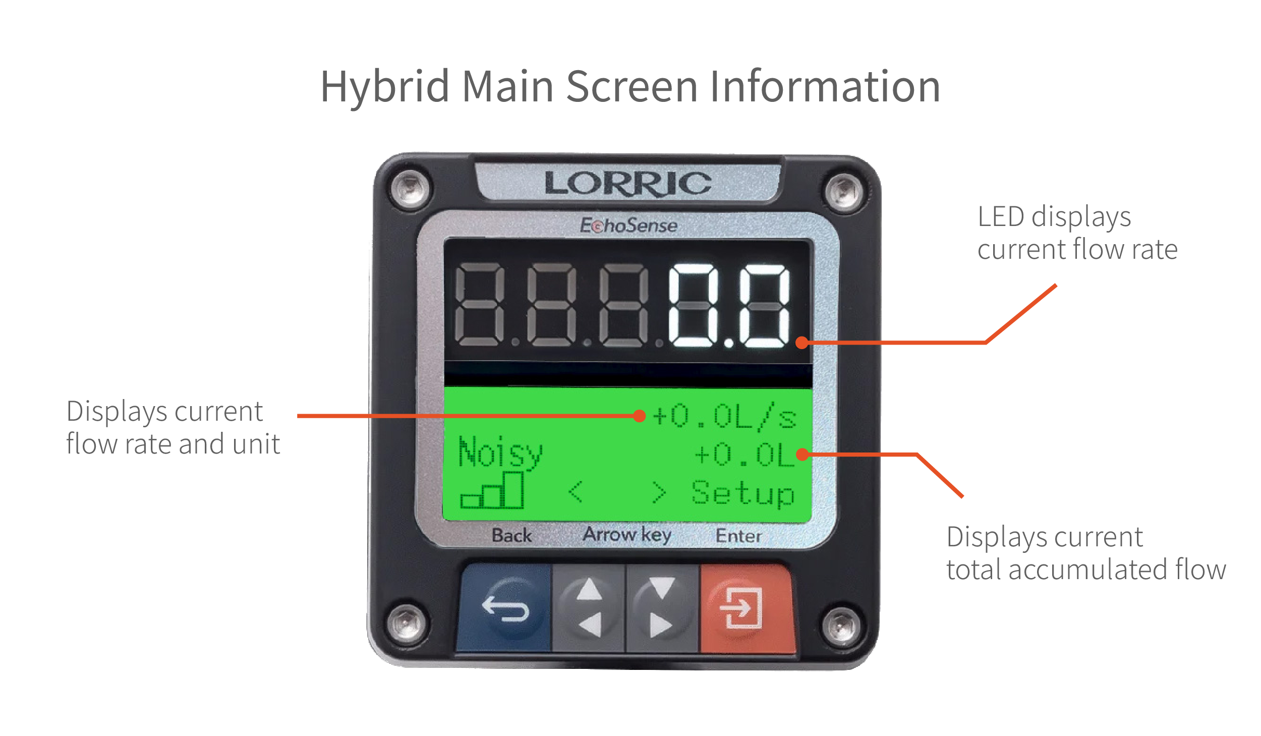
Application Scenario the Hybrid Page provides real-time monitoring of two key metrics—instantaneous flow rate and cumulative flow rate—allowing users to make prompt adjustments based on current conditions. This dual-data display is designed to optimize operational decision-making and efficiency.
## Hybrid Page Setup Guide
Follow these steps to configure the Hybrid Page:
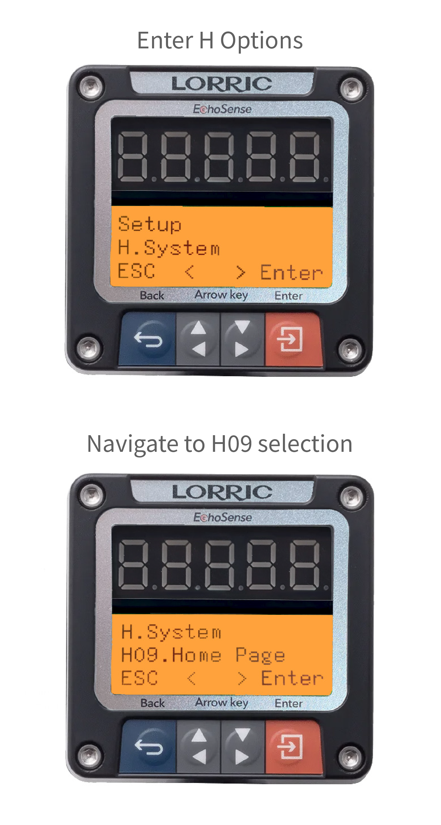
1. **Open the Settings Menu**:
* Navigate to the **Settings** screen and select **Option H**.
* Press the button to enter the settings submenu **H09: Boot Screen Settings**.
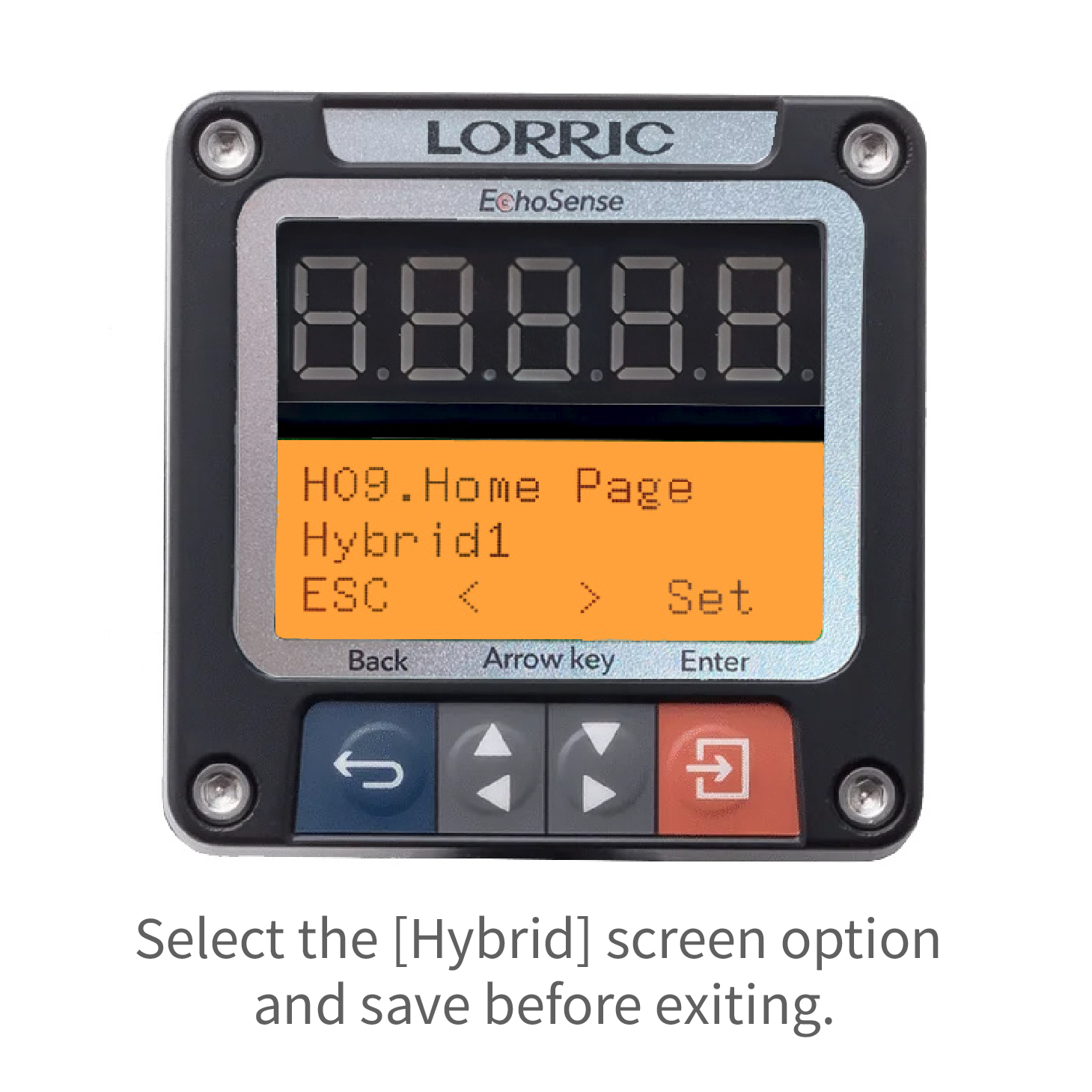
2. **Select the Hybrid Page Option**:
* In the settings menu, locate and select the "Hybrid Page" option.
3. **Set Parameters**:
* Adjust display parameters based on operational needs, such as the flow rate display format or alarm threshold indicators.
4. **Save Settings and return**:
* Once adjustments are complete, click the **"Save"** button to apply and retain the settings.
## HybHybrid Page Function Page Display