> For the complete documentation index, see [llms.txt](https://docs.lorric.com/qr/llms.txt). Markdown versions of documentation pages are available by appending `.md` to page URLs; this page is available as [Markdown](https://docs.lorric.com/qr/fp-as310-r-english-v5/installation-and-setup/mechanical-installation.md).

# Mechanical installation

## Important! Read Before Installing

{% hint style="danger" %}

#### **Installation Sequence for PVC Piping**

The flowmeter housing and internal paddlewheel are made of polycarbonate (PC). Contact with PVC cement, PVC cement vapors, or pipe lubricant may damage these components.

Install and fully cure the PVC pipe fittings and adapters **before** attaching the tee fitting and flowmeter body. Make sure that the PVC cement is completely dry and that no residue remains inside the pipe. Do not allow PVC cement or lubricant to drip onto the flowmeter housing or enter the paddlewheel assembly.
{% endhint %}

The following improper usage or installation practices may damage the flowmeter and reduce product lifespan. Such damage is **not covered under warranty.**

* EPDM seal material only compatible with certain chemicals, but not oil.
* If the paddle wheel flowmeter is not able to be aligned with the main pipe or is taken as supported point on the pipeline, the flowmeter may bear unexpected force which could shorten usage life and cause water leakage.
* During the installation, it is better to use hands to lock the union nuts until there is no water leakage instead of using tools which could damage the flowmeter.
* Inaccurate piping may cause liquid leakage and lead to the paddle wheel flowmeter’s damage.
* When valving, water hammer should be carefully avoided to prevent paddle wheel flowmeter damage.
* The operational device of the paddle wheel flowmeter is not UV resistant. Therefore, we suggest to cover it with protector if installed outdoors.
* The seller will not be responsible of free maintenance for any defect or malfunction incurred by individual causes.
* If the paddlewheel flowmeter is transported with it's piping system to another site without protection it could be damaged.
* The LCD display screen should not be exposed to direct sunlight that could cause visibility issues and a shorter usage life. Therefore, installing the flowmeter under direct sunlight should be avoided or with a sunlight protector is recommended.
* The flow volume measurement of LORRIC’s paddle wheel flowmeter is based on the rotating mechanism of the paddle wheel. Paddle or axel could be lost under long-term abrasion or impact by external forces.Users should pay careful attention to any equipment that may cause the above damage.
* When installing the paddle wheel flowmeter there should be an appropriate amount of spacing for union and flange installation. If not, the following accidents may occur:
  1. Crack on union nut
  2. Crack on adaptor
  3. Stripped T-connector thread
  4. Water leakage due to insufficient compression or missing sealing

***

## Installation Guide

{% stepper %}
{% step %}

### Selecting Installation Location

* **Ensure Full Pipe:** Install the flowmeter on a fully filled vertical pipe segment. If installed on a horizontal pipe, avoid areas prone to air bubble accumulation (top of pipe) or sediment deposition (bottom of pipe). Presence of air bubbles may cause large, non-repeatable measurement errors.
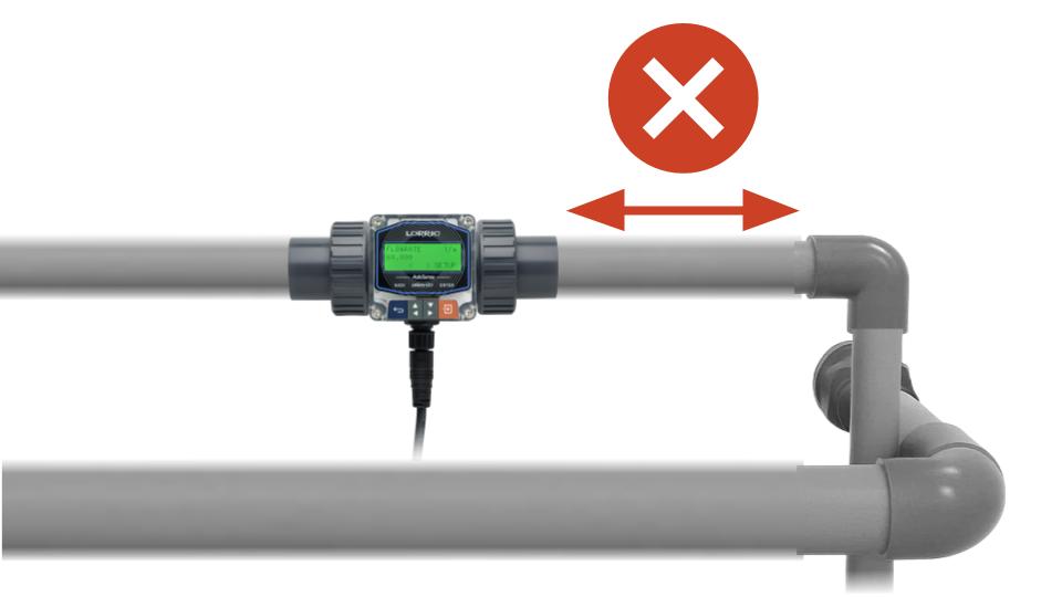
* **Install on Fully Developed Flow:** Mount the flowmeter on a pipe section with uniform, stable flow. Avoid locations near components that disturb flow, such as pipe reducers, elbows, valves, or pumps.
* **Protect the Main Unit:** Do not expose the LCD directly to sunlight. If necessary, add a sunshade. Direct sunlight can reduce readability and shorten LCD lifespan.

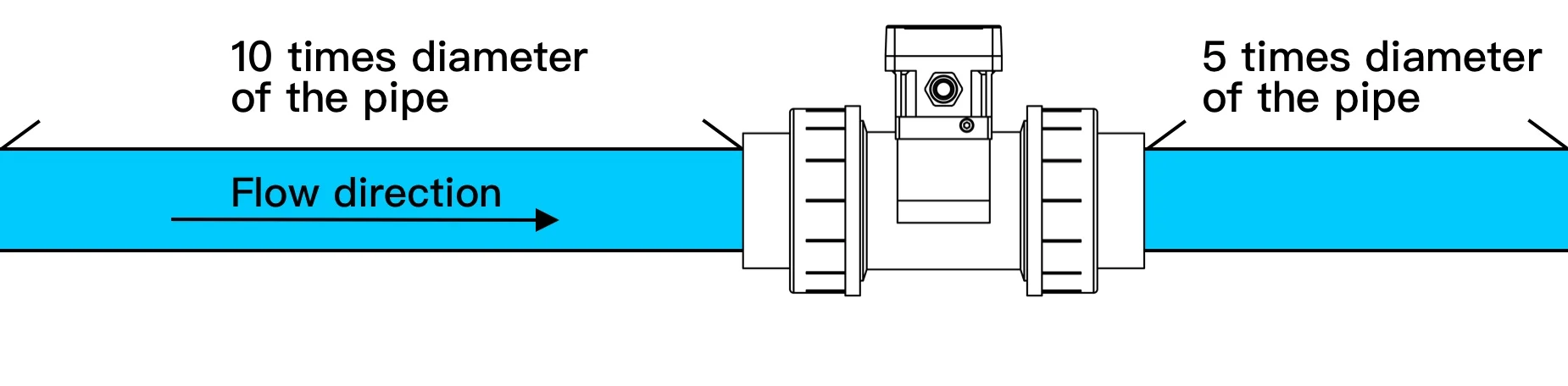
#### Straight Pipe Requirements – 10D / 5D Guideline

To ensure stable and uniform flow for accurate measurement, install the flowmeter away from components that may disturb flow velocity. Follow these guidelines:

* **Upstream (before the flowmeter):**\
  Provide a minimum straight pipe length of 10 × pipe diameter (10D). Do not place elbows, tees, valves, reducers, expanders, pump outlets, or any component that may disturb the flow.
* **Downstream (after the flowmeter):**\
  Provide a minimum straight pipe length of 5 × pipe diameter (5D) to prevent downstream pressure fluctuations from affecting measurement stability.
* **Installation Direction:**\
  Align the flowmeter according to the flow direction arrow on the housing. Ensure it matches the actual flow direction.

<figure><img src="/files/ahGtG3bazom7G8iuMc0E" alt=""><figcaption></figcaption></figure>

```
Example: Straight Pipe Lengths for DN25 (25 mm Nominal Diameter)
Pipe Diameter (D): 25 mm
Upstream Straight Pipe: 10 × D = 10 × 25 mm = 250 mm (~25 cm)
Downstream Straight Pipe: 5 × D = 5 × 25 mm = 125 mm (~12.5 cm)
```

**Additional Recommendations**

* For sites near pumps, strong pulsations, or multiple upstream/downstream fittings, increase upstream straight pipe to 15–20 × D or use a flow conditioner.

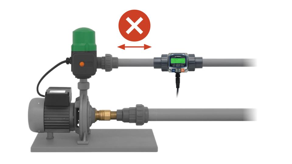
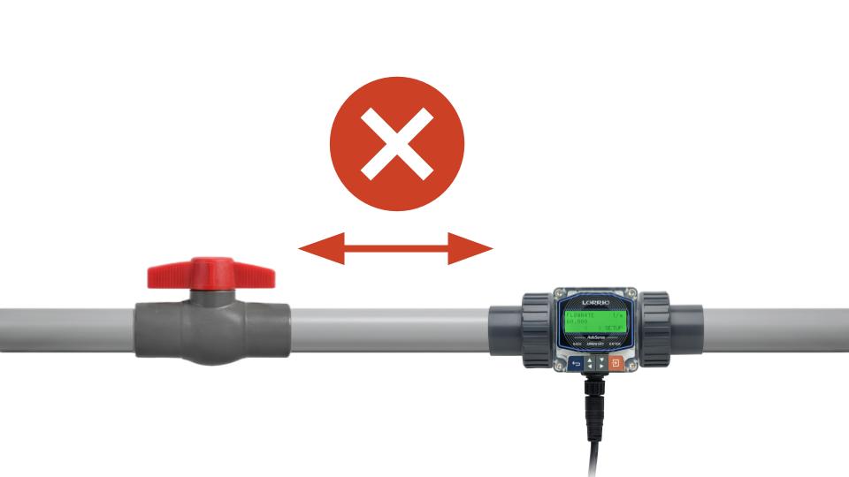
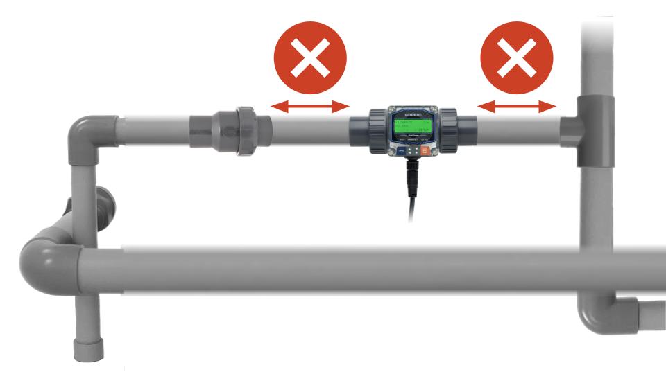
**Avoid Installing the Flowmeter Near:**

<div><figure><img src="/files/HP5V0l0hlguAq13Yt6lm" alt=""><figcaption><p>Near Pumps</p></figcaption></figure> <figure><img src="/files/pYAV2GF2B8op9zDcMORm" alt=""><figcaption><p>Near Valves</p></figcaption></figure></div>

{% hint style="info" %}
This flow meter measures flow rate using a rotating mechanism. Under long-term wear or external impact, the blades or spindle may detach. During installation, please ensure that no downstream equipment (such as pumps) can be damaged as a result of this.
{% endhint %}

{% hint style="info" %}

#### Installing Before Valves

We recommend installing the flow meter upstream (before) any valves.

When liquid passes through a valve, it creates turbulence and disrupts the flow. If you must install the flow meter *after* a valve, you will need a much longer section of straight pipe to allow the liquid to stabilize and return to a smooth, uniform flow. Otherwise, the reading will be inaccurate. This same rule applies to any other piping components that disrupt the flow field.
{% endhint %}

<div><figure><img src="/files/3EvR5uLc5jlqiVPwjPXA" alt=""><figcaption><p>Near tees, reducers, or expanders</p></figcaption></figure> <figure><img src="/files/bgXrbuGoFrSHYHGG2e81" alt=""><figcaption><p>Near Elbows</p></figcaption></figure></div>

{% endstep %}

{% step %}

### Installation Orientation & Flow Direction

#### Installation Orientation

* Vertical Pipe: Install the flowmeter on upward flow.
* Horizontal Pipe: Install at a fully filled section, e.g., the lower side of a sloped pipe or the bottom of a U-shaped pipe.

<table data-header-hidden><thead><tr><th valign="top"></th><th valign="top"></th></tr></thead><tbody><tr><td valign="top"><strong>Vertical Pipe:</strong></td><td valign="top"><strong>Horizontal Pipe:</strong></td></tr><tr><td valign="top"><img src="https://docs.lorric.com/qr/~gitbook/image?url=https%3A%2F%2F498068148-files.gitbook.io%2F%7E%2Ffiles%2Fv0%2Fb%2Fgitbook-x-prod.appspot.com%2Fo%2Fspaces%252F-M7fZsO11LItbPHrVN6W%252Fuploads%252FgAPXE05T5VAWVPKNLQUN%252FVertical-pipe-en.png%3Falt%3Dmedia%26token%3D6223a77f-dde5-4c0b-a6f5-0d34d59b9856&#x26;width=768&#x26;dpr=3&#x26;quality=100&#x26;sign=2f1fae9e&#x26;sv=2" alt="" data-size="original"></td><td valign="top"><img src="https://docs.lorric.com/qr/~gitbook/image?url=https%3A%2F%2F498068148-files.gitbook.io%2F%7E%2Ffiles%2Fv0%2Fb%2Fgitbook-x-prod.appspot.com%2Fo%2Fspaces%252F-M7fZsO11LItbPHrVN6W%252Fuploads%252Fx0TJEOopWt9x7BYzX4ex%252FHorizontal-pipe-en.png%3Falt%3Dmedia%26token%3D167c7c76-f87b-4cd2-a299-0f351854912c&#x26;width=768&#x26;dpr=3&#x26;quality=100&#x26;sign=296066f0&#x26;sv=2" alt=""></td></tr><tr><td valign="top">Install the flowmeter on upward flow.</td><td valign="top"><ul><li><strong>Ensure Full Pipe Flow:</strong> Choose a location where the pipe is always completely filled with liquid (e.g., the lower side of a sloped pipe or the bottom of a U-shaped pipe).</li><li><strong>Avoid Top and Bottom Placements:</strong> Do not install the meter at the dead top (vulnerable to air bubbles) or dead bottom (vulnerable to sediment buildup) of the pipe.</li><li><strong>Avoid Exact Horizontal Alignment:</strong> Avoid installing directly at the 3 o'clock or 9 o'clock positions. This causes the paddlewheel to tilt to one side, leading to measurement errors and a shorter lifespan.</li></ul></td></tr></tbody></table>

**Flowmeter Orientation**

Install the flowmeter on the side, slightly above, or slightly below the pipe. Avoid the top or bottom to prevent interference from bubbles or sediment.

* **Recommended Positions: Slanted Upward, Slanted Downward**

![](/files/9iLIlcnmpKCepPua2n1z)

* **Avoid:** Right Above, Right Beneath, or at side

![](/files/wSDLkPRZEu837D58RtcS)

**Please notice the air bubble in the pipe to avoid measurement error.**\
If the location of installation for the paddlewheel is close to a tank where pressure is low. We recommend installing a valve at the pipe exit to avoid generating any air bubbles.&#x20;

{% hint style="warning" %}
If air bubbles frequently generate in the pipe it may lead to over 5% non-reproducible measurement error which should be avoided.&#x20;
{% endhint %}

{% endstep %}

{% step %}

### Product Installation Steps

1. Take off union adapter and nuts, paddle set, and device from T-connector
2. Install union adapter and nuts with pipe: Install the union adapter and nuts to the pipe with glue. Before going to the next step, the glue should be completely dry.
3. Lock T-connector and pipe with union adapter
4. Install paddle set and seals with T-connector: The arrow sign on the top of the paddle set means the direction of flow, the top side of the arrow sign means the direction of line-out. As below image, please refer to it before installation.
5. Install device to the paddle base and rotate it clockwise to the end. With orientation design, please watch the installation direction and do not force it.
6. Fix device with paddle base through the side of it: The screws for fixing the device with the paddle set are not leakproof. Please avoid excessive force when screwing in the device which may cause damage.

![](/files/FXyaTorzNzF8FQWrYSd4)

{% endstep %}

{% step %}

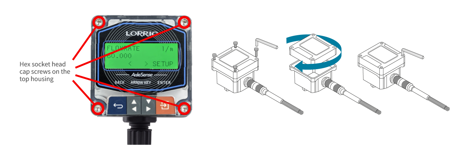
### R**otating the display screens’ direction**

<figure><img src="/files/acu2h3Jkls0EpvTb0ewZ" alt=""><figcaption></figcaption></figure>

<mark style="color:red;">**Warning: Do not use excessive force when disassembling or rotating the host, avoid pulling or damaging the wiring, and check whether the wires are disconnected.**</mark>

1. Please turn off the device and unplug before disassembling it.
2. Take off four hex socket head cap screws on the top housing according to above image.
3. Seperate top and bottom housing.
   1. Be aware when separating the top and bottom housing because there are many wires connecting both.
4. Rotate top housing to a desired viewing orientation.
   1. Do not rotate the top housing too many times to prevent the cables from being damaged from unnecessary pulls.
5. In the bottom housing there is an O-ring with an inner groove for a thread hole . For it to work properly, please confirm there is no particle, fiber or any object that may break the sealing function before attaching the top and bottom housing.
6. Combine top with bottom housing.
7. Tighten four screws on top housing.
   1. Too much torque may damage the device.
8. Finish.

{% endstep %}
{% endstepper %}


---

# Agent Instructions
This documentation is published with GitBook. GitBook is the documentation platform designed so that both humans and AI agents can read, navigate, and reason over technical content effectively. Learn more at gitbook.com.

## Querying This Documentation
If you need additional information that is not directly available in this page, you can query the documentation dynamically by asking a question.

Perform an HTTP GET request on the current page URL with the `ask` query parameter, and the optional `goal` query parameter:

```
GET https://docs.lorric.com/qr/fp-as310-r-english-v5/installation-and-setup/mechanical-installation.md?ask=<question>&goal=<endgoal>
```

`ask` is the immediate question: it should be specific, self-contained, and written in natural language.
`goal` is optional and describes the broader end goal you are ultimately trying to accomplish on behalf of the user. GitBook uses it to tailor the answer towards what is most useful for that goal.

The response will contain a direct answer to the question and relevant excerpts and sources from the documentation.

Use this mechanism when the answer is not explicitly present in the current page, you need clarification or additional context, or you want to retrieve related documentation sections.