> For the complete documentation index, see [llms.txt](https://docs.lorric.com/qr/llms.txt). Markdown versions of documentation pages are available by appending `.md` to page URLs; this page is available as [Markdown](https://docs.lorric.com/qr/fp-as310-r-english-v5/communication/rs485-setup.md).
# RS485 Modbus RTU
{% hint style="info" %}
RS485 is enabled **only in the Main Screen** state. When the device is in a **settings** or **parameter editing** screen, RS485 will not respond to any Modbus commands.
{% endhint %}
### **Specifications**
| Baud Rate | 9600, 19200, 38400, 57600 |
| --------------------------------- | ---------------------------------------------------------------------------------- |
| Wiring | 2-wire |
| Maximum Nodes on the Same Network | 256 (under standard unit load conditions, where each device counts as 1 unit load) |
### RS485 2-Wire Wiring Diagram
* **Black:** RS485 (B−), **Green:** RS485 (A+)
This function operates only when the brown and blue lines of the DC power supply are powered.\
For clarity, the DC power lines are omitted in this diagram. Refer to the **DC Power Wiring Diagram** for details.
{% hint style="danger" %}
Do not confuse RS485 wiring with the power lines; miswiring may damage the device, and repair costs are the user’s responsibility.
{% endhint %}

{% hint style="info" %}
## **Wiring Recommendations**
1. Use **24 AWG shielded twisted pair** for RS485, daisy-chaining each device. Avoid ring or star topologies.
2. For long runs, place **termination resistors (typically 120 Ω)** at the master and far-end device; adjust based on cable specs.
3. If communication is unstable, add **bias resistors** near the master to improve signal stability.
4. For 6-core cables, trim to the minimum required length and connect the shield to ground.
5. In areas with heavy interference, implement **multiple query retries** in software to distinguish signal noise from device offline errors.
{% endhint %}
### RS485 Modbus RTU Parameter Configuration
Follow the steps below to configure RS485 Modbus RTU parameters:
{% stepper %}
{% step %}
#### **Set Basic Parameters**
* Refer to the [**Parameter Settings**](/qr/fp-as310-r-english-v5/installation-and-setup/parameter-setup.md) page and complete the following steps: **Language Setting, Pipe Settings:A02:** Pipe Standard, **A04:** Pipe Outer Diameter, **A06:** Pipe Wall Thickness, **A08:** Pipe Material
* Execute **Z03 (Automatic Initialization)**.
{% endstep %}
{% step %}
#### **Wiring Setup**
Connect the RS485 Modbus RTU wiring according to the instructions on this page.
{% endstep %}
{% step %}
#### **E04 Modbus ID (Communication Protocol Application)**
Set **E04** to assign the flowmeter’s **Modbus Slave ID** on the RS485/Modbus network.
* Ensure that each device on the same bus has a **unique ID** to avoid communication conflicts.
* This parameter **cannot be modified via RS485**.
{% endstep %}
{% step %}
#### **E05 Baud Rate**
Set **E05 Baud** to specify the flowmeter’s **Modbus communication speed** (Baud Rate).
* The **Master** and **Slave** devices must be set to the **same Baud Rate** for proper communication.
* This parameter **cannot be modified via RS485**.
{% endstep %}
{% step %}
#### **Return to Main Screen**
Return to the **Main Screen** (green LED). RS485 communication is enabled **only on the Main Screen**.
{% endstep %}
{% step %}
#### Test Read/Write Memory
Refer to the [**Modbus RTU Protocol**](/qr/fp-as310-r-english-v5/communication/modbus-rtu-protocol.md) to test the memory for reading and writing. This parameter provides 4 types of byte packet formats.
| | |
| ---------------------------------- | -------------------------------------------------------------------------------------------------------------------------------------------------------------------------------------------------------------------------------------------------------------------------------------------------------------------------------------------------------------------------------------------------------------------------------------------------------------------------------------------------------------------------------------------------------------------------------------------------------------------------------------------------------------------------------------------------------------------------------------------------------------------------------------------------------------------------------------------------------------------------------------------------- |
|
Communication Format
|
bit order: lsb first byte order: big endian Data bits: 8 Parity: None Stop bits: 1
Floating point number follows IEEE754-1985. The float32 below stands for 32bits Single precision floating point number.
|
| **Memory Definition and Function** |
Modbus-accessible memory is divided into two types: Read-Only (RO) and Read/Write (RW).
Read-Only Memory (RO):
Primarily stores flowmeter status information, such as real-time flow.
Each write operation can only modify one parameter at a time.
If the parameter occupies 1 register, use function code 06.
If the parameter occupies 2 registers, use function code 30.
|
{% hint style="info" %}
In Modbus RTU communication, a Register is the basic unit for memory communication, with a length of 2 bytes (16 bits).\
A Byte is the basic unit for data transmission, with a length of 8 bits.
{% endhint %}
{% endstep %}
{% endstepper %}
Modbus RTU Example – Reading Float32 Data(Click to expand)
### Modbus RTU Example – Reading Float32 Data
Using a Read-Only memory read command (04) as an example, this section explains how to send a command and parse the returned data into a decimal value when the accumulated flow is **5,000.0** liters.
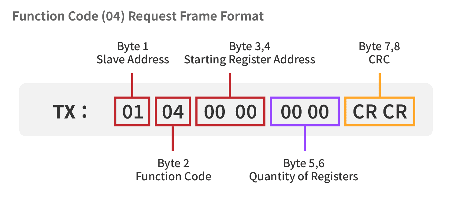
**Read-Only Memory – Read Command (04) Format**
Modbus RTU Example – Read-Only Memory Read Command (04)(Click to expand)
### **Modbus RTU Example – Read-Only Memory Read Command (04)**
**Master Sends Read Command (TX Frame)**
According to device specifications, the accumulated flow is stored in **Float32 format**, occupying **2 registers (4 bytes)**; therefore, the quantity to read should be set to **00 02**. The master must send Modbus function code 04 (Read Input Registers) to read 2 registers starting from address 0000.
```
TX: 01 04 00 00 00 02 71 CB
```
* Slave Address = 01
* Function Code = 04
* Starting Register Address = 00 00
* Quantity to Read = 00 02 (2 registers)
* CRC Checksum = 71 CB
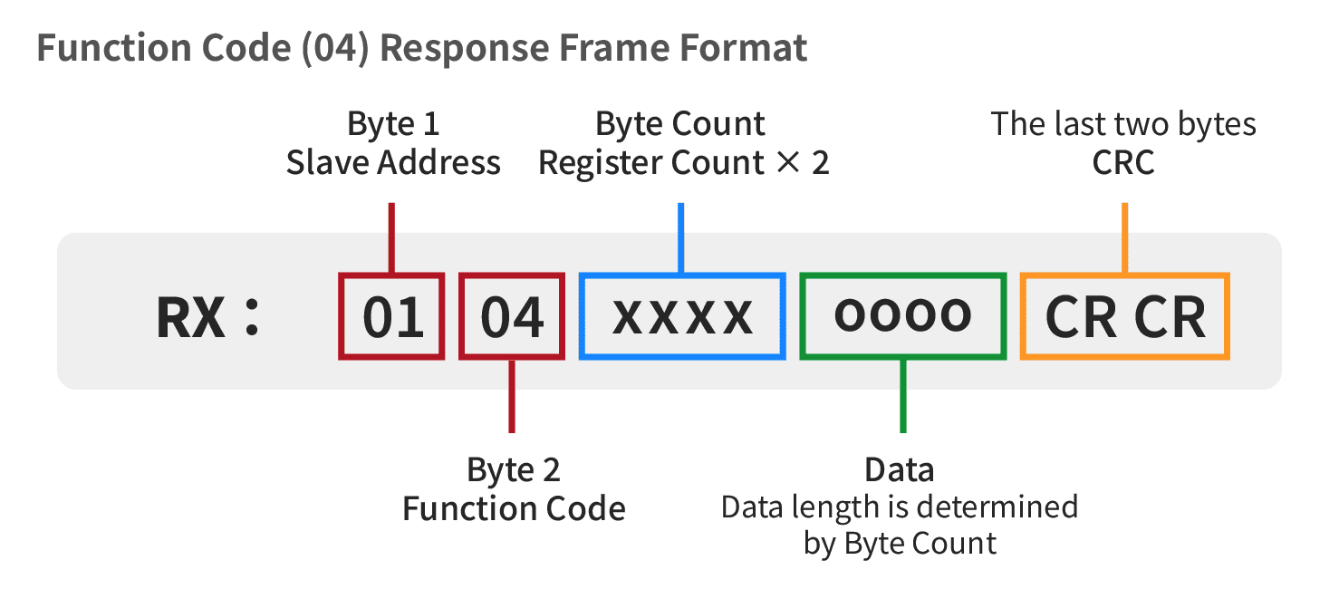
**Slave Response Data (RX Frame)**
After receiving the read request, the slave returns the internally stored **5,000.0 liters (Float32)** data, packaged as **4 bytes** according to **Modbus Register Big Endian** (high byte first) and **IEEE 754 Float32** format.
```
RX: 01 04 04 45 9C 40 00 1F 66
```
* Slave Address = 01
* Function Code = 04
* Byte Count (Number of Data Bytes) = 04 (4 Bytes)
* Data (Data Field) = 45 9C 40 00
* CRC Checksum = 1F 66
**Data Parsing and Conversion (Back to Decimal)**
**Step A: Arrange the Data**\
Since the device uses **Big Endian** format, the most significant byte comes first. Therefore, the 4 bytes are kept in the received order and combined as:\
`459C4000₁₆`
**Step B: Decode the Float32 Structure (SEM: S = Sign, E = Exponent, M = Mantissa)**\
Convert `459C4000₁₆` into a 32-bit binary number for IEEE 754 Float32 interpretation.

**Partial Binary Value Explanation**
* **S (Sign bit)** = 0 (1 bit) → 0 means a positive number
* **E (Exponent bits)** = `10001011` (8 bits) → 139₁₀\
Actual exponent = 139 − 127 = **12**
* **M (Mantissa bits)** = `001110001...` (23 bits) → the significand is **1.M**
**Step C: Calculate the Value**
According to the IEEE 754 Float32 format, the calculation is as follows.\
The exponent bits `10001011₂` equal 139₁₀, so the actual exponent is 139 − 127 = 12.
* The mantissa bits are 00111000100000000000000, giving a significand of 1.001110001...
After shifting the binary point 12 places to the right and converting to decimal:
Value = 2¹²+2⁹+2⁸+2⁷+2³ \
\= 4096+512+256+128+8 \
\= 5000.0
Therefore, the Modbus RX response data `01 04 04 45 9C 40 00 1F 66` represents a cumulative flow value of **5000.0 liters**.
### **Modbus Data Format Converter**
Below is a sample **HTML/CSS/JS (CodePen example)** of a simple converter used to convert an **8-digit hexadecimal value** into a **Float32** number.
{% embed url="" %}
---
# Agent Instructions
This documentation is published with GitBook. GitBook is the documentation platform designed so that both humans and AI agents can read, navigate, and reason over technical content effectively. Learn more at gitbook.com.
## Querying This Documentation
If you need additional information that is not directly available in this page, you can query the documentation dynamically by asking a question.
Perform an HTTP GET request on the current page URL with the `ask` query parameter, and the optional `goal` query parameter:
```
GET https://docs.lorric.com/qr/fp-as310-r-english-v5/communication/rs485-setup.md?ask=&goal=
```
`ask` is the immediate question: it should be specific, self-contained, and written in natural language.
`goal` is optional and describes the broader end goal you are ultimately trying to accomplish on behalf of the user. GitBook uses it to tailor the answer towards what is most useful for that goal.
The response will contain a direct answer to the question and relevant excerpts and sources from the documentation.
Use this mechanism when the answer is not explicitly present in the current page, you need clarification or additional context, or you want to retrieve related documentation sections.